
Available on all Air, Remote, and Water Cooled Condensing Units and Evaporators.
Three times faster than electric defrost systems. Provides reduction in box temperature rise, minimal product deterioration and reduced power consumption resulting in energy savings. Shorter defrost cycle periods provide increased refrigeration time allowing smaller equipment sizing and lower initial equipment costs. Can be used with single or multiple evaporator systems. Multiple evaporators can all be defrosted together.
All extra system components such as liquid line solenoid valve, evaporator TXV (thermostatic expansion valve), check valves, hot gas solenoid valve, three-way valve, and crankcase pressure regulator are all installed and pre-piped at the factory. This results in a faster and simpler system installation with significant savings on installation costs.
Eliminates field installation of extra hot gas pipe between condensing unit and evaporator resulting in simpler design and reduced installation cost.
Provides shorter defrost periods and faster return to refrigeration cycle. Eliminates thermal lag (time delay) as found with conventional thermostat controls. Eliminates wiring the evaporator defrost controls back to the condensing unit, reducing installation costs.
Drain pan heater is energized two minutes prior to start of defrost cycle. This ensures all water from melting frost is kept warm throughout the drain line, preventing line blockage. It also maximizes the heat transfer effect by allowing hot gas to directly enter the evaporator coil.
Crankcase pressure regulator protects compressor from excessive suction pressures reducing motor overloads. Two suction accumulators (one with a liquid/suction heat exchanger) provide maximum heat transfer and liquid trapping capability during both the defrost and refrigeration cycle.
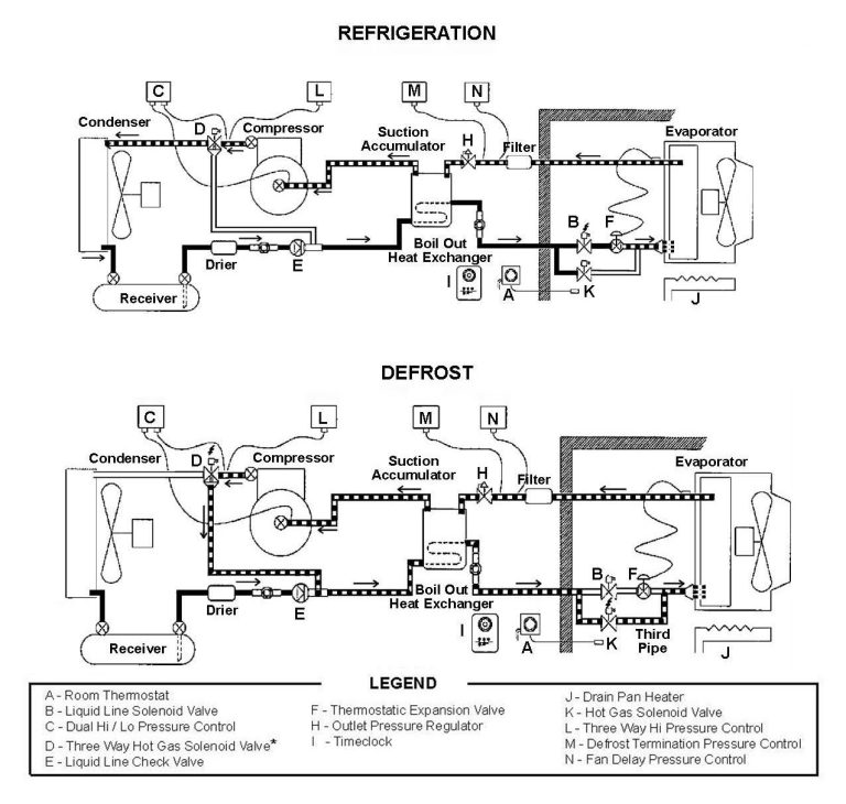
The refrigeration cycle results in frost formation on the surface of the evaporator. This frost will eventually build up to the point where it will restrict the air flow causing a loss of refrigeration capacity. To prevent this, (I) a timeclock, usually set to repeat every 6 or 8 hours, initiates a defrost cycle which melts the frost.
The clock de-energizes (closes) the liquid line solenoid valve which causes the compressor to pumpdown and shut off from the low pressure control. The clock also energizes the (J) drain pan heater in the evaporator and timer relay which after a two minute delay energizes (opens) the 3-way valve and (K) hot gas solenoid valve which then builds up pressure in the evaporator causing the low pressure control to close and start the compressor.
The hot discharge gas from the compressor flows through the 3-way valve, Hot gas valve and check valve forcing all the liquid left in the liquid line into the evaporator. If pressure builds up too high the (L) 3-way valve pressure control will de-energize the solenoid valve and allow pressure to relieve through the condenser. Pressures within the evaporator will remain steady and once all the frost has melted the pressure will rise until the (M) defrost termination pressure control energizes the timeclock’s internal solenoid terminating the defrost cycle. The 3-way valve, hot gas valve solenoids are then de-energized. The liquid line solenoid valve opens and the compressor continues to run.
The evaporator fans do not start up until the pressure in the evaporator is low enough to close the (N) Fan delay control. By delaying the fans this allows any moisture left on the coil to drain away or freeze. As soon as the evaporator fans are energized the system will then resume back to the refrigeration cycle.
As the box temperature rises, the (A) room thermostat energizes the (B) liquid line solenoid valve. This allows refrigerant to enter the evaporator, build up pressure, cause the (C) low pressure control to energize the compressor contactor and start the compressor. The compressor’s hot discharge gas is piped out to the condenser through the (D) de-energized 3-Way valve.The hot refrigerant gas is condensed by the cooler ambient air from the condenser fan.
The liquid then flows to the receiver through the (E) opened check valve and on through the coiled liquid line within the suction accumulator (this performs the function as a suction to liquid heat-exchanger). The sub-cooled liquid then flows through the liquid line solenoid valve (energized/open) and on to the (F) TXV (Thermostatic expansion valve).
The refrigerant is then directed through the distributor at a lower pressure and flows into the evaporator. Refrigerant is prevented to flow past the (G) closed checkvalve.
The refrigerant liquid / vapor mixture is then boiled by the warmer box air from the evaporator fan. The refrigerant vapor then flows though a (H) crankcase pressure regulator preventing a motor overload from high suction pressures and enters the two suction accumulators and on to the compressor.